
This page provides basic introductory information pertaining to balancing and balancing machines and provide guide lines for those unfamiliar with balancing and first time users of balancing machines. Visit our FAQ for more detailed information. This page and the FAQ should be considered as introductory explanations and general guidelines. Refer to the relevant ISO standards for more details and the balancing machine user manual for more details of operational descriptions.
Feel free to contact us should you have any balancing machine requirement.
Table of Contents
What is an unbalance?
A rotor has axes around which it “naturally prefers” to rotate usually called the principal axes. Intuitively, they are axes which pass through the center of mass and the mass distribution around these axes are uniform and symmetrical. A physical rotor has a physical axis of rotation,i.e. engineered axis obtained through machining processes. However due to the non uniformity in mass distribution of the rotor, the physical axis of rotation and the principal axis do not coincide. Because of the non co-incident axes, now the mass distribution around the real-life axis of rotation is non uniform. This non uniformity in mass is quantified and shows up as an unbalance of the rotor.
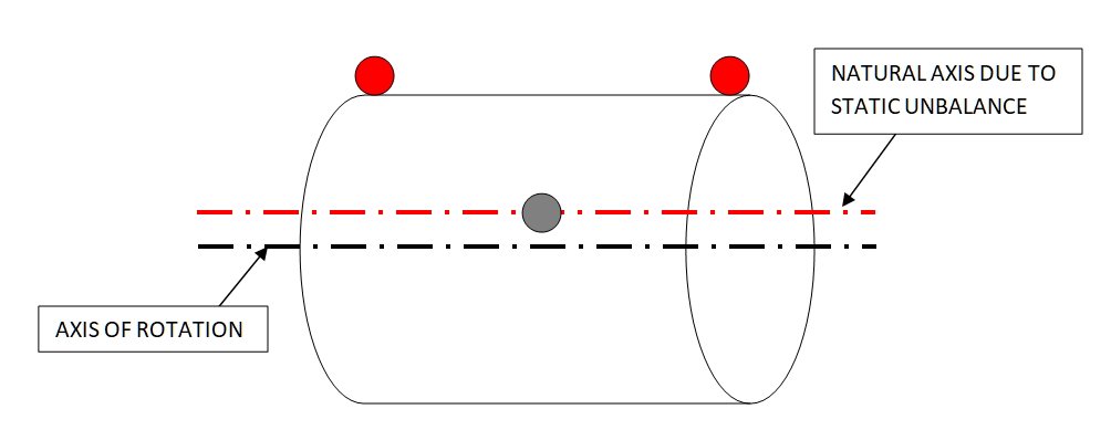
When the mass distribution is non uniform purely in the radial direction, but uniform axially, only the center of mass and the principal axes is shifted parallel to the axis. of rotation. This is a purely static unbalance
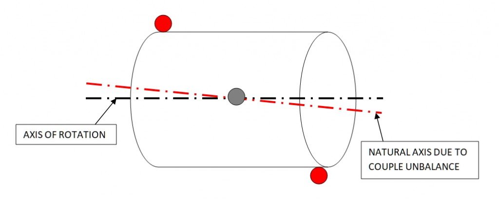
When mass distribution is such that the axis of rotation and principal axes intersect at the center of mass, this is a purely couple unbalance. This typically happens when the mass distribution is symmetric about the center of mass axially, but equal and opposite radially on either side of the center of mass.
Real rotors have a combination of static and couple unbalance. The relative effect of each type of unbalance dependent on the shape and size of the rotor.
What causes an unbalance?
Real life processes are not perfect. All manufacturing processes are performed to within a specified tolerance. The error occurring in every stage of the manufacturing process affects the mass distribution of the rotor. Some examples would be a casting where the flow of the metal is not uniform, or castings with blow-holes in them. Another example would be operations like welding during fabrication or rework may also create unbalance due to weld and thermal effects.
What are the effects of unbalance on a machine?
The non uniform mass distribution causes centrifugal forces to be generated. These forces are transferred to the supports of the rotor such as the bearing, bearing housing and eventually the frame of the machine. The unbalance force is thus a cyclic and repetitive forcing. This causes reduced bearing life, component life, increased loads and fatigue. The vibration induced may also be above acceptable limits from the aspect of Noise, Vibration and Harshness(NVH).
What is the relationship between unbalance and vibration?
Unbalance is a physical mass quantity. This mass causes a centrifugal force inducing the vibration. One of the effects of unbalance on a rotating rotor is vibration. However, unbalance is not the only source of vibration. Unbalance generates a characteristic type of vibration. The vibration produced by an unbalance has the same frequency as that of the rotating component, what is called 1x. I.e, if say a rotor is rotating at 1200 rpm, i.e. 20 cycles per second or 20 Hz, the vibration produced by the unbalance will be at 1x the running speed, i.e. 20 Hz. In a machine, other sources of vibration may also be present say at multiple harmonics like 3x, 5x and also from other transmission elements such as belts, gears, bearings etc. So, balancing a rotor is critical for vibration reduction. However, a well balanced rotor on assembly may still run with vibration if other aspects of mounting and assembly are not taken care of.
What is balancing of a rotor
The process of reducing the unbalance of a rotor to within a specified tolerance value is called balancing. In common use, the term can also mean to check if the rotor is having an unbalance within the specified tolerance. Depending on the application, the unbalance on the rotor can be either corrected or the rotor rejected.
A rotor is normally balanced by loading it and checking it’s unbalance on a balancing machine. The balancing machine spins the rotor to a specified speed, measures the unbalance using it’s sensors and balancing instrumentation and displays the unbalance value to the operator. The operator may decide to add or remove weights at the indicated location to bring the rotor within balance.
What are the effects / benefits of balancing a rotor?
A balanced rotor generates lower centrifugal forces, and as a consequence lower vibration levels. This enables machines to operate faster and last longer improving the productivity and reliability. A well balanced rotor generates lower stresses on the bearings prolonging the life of the components.
What is a balancing machine?
Broadly, a balancing machine is a measuring machine designed to tell the operator where masses have to be added or removed on a rotor to bring an unbalanced rotor to within a specified balancing tolerance.
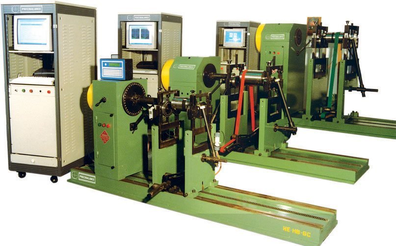
In general, the balancing machine is equipped with a stand or bed. The rotor supports where the component is mounted is fixed on this stand/bed. A drive arrangement to spin the job at a pre determined speed is provided. RPM sensors are used to measure the rotating speed. Vibration sensors are used to measure the vibration signals from the component. A measurement, processing and displaying system processes and convert this sensor data to human readable unbalance results.
Modern balancing machines are usually computerized balancing machines wherein the indication of the unbalance location is shown on a PC. Balancing machines may come with options of either automatic or manual unbalance correction depending on the cost and productivity considerations.
In addition, modern balancing machines like Precibalance balancing machines come with standard features such as automatic calibration, tooling error compensation, placeweights program, report generation, remote angle electronic protractor function etc to balance rotors quickly and efficiently in an industrial setting.
How is unbalance interpreted on a balancing machine?
Unbalance is a vector quantity, i.e. it has a magnitude and a direction. The magnitude of the unbalance is defined as a composite product (multiplication) value of mass (m) times radius (r). m x r. This is the measured quantity internally in balancing machines. The user feeds a radius of correction desired r, and the machine computes the unbalance mass m based on the measured unbalance value. The direction of the unbalance is the angle measured from a known reference on the balancing machine. Thus the units in metric will be g-mm. An example of unbalance would be 10 g-mm @ 45 degrees. The reference could be fixed on the rotor, like a reflective sticker, or internally in the machine. In some literary references, the unbalance is referred in terms of eccentricity, measured in microns for the metric system. This measurement normalizes the unbalance with respect to the rotor weight. I.e, it is the unbalance divided by rotor weight or mxr/M, where M is the mass of the rotor. While doing the division, take care to use consistent units, i.e. if mxr is units of g-mm, M should be in grams.
For practical unbalance correction, one needs to know the unbalance value in a weight value say grams. This is achieved by dividing the unbalance value by the radius. Thus a 50 g-mm unbalance at 100 mm radius, needs a correction of 50 g-mm/100 mm, i.e. 0.5 grams. Modern balancing machines supplied by Precibalance indicates both the g-mm value as well as the value in grams as well as a combination of many other non metric mass and length units such as oz-in, lb-in etc.
For interpretation of the effect of unbalance, the magnitude is the relevant value. The angle is relevant for determining the location of the unbalance. The angle can be any value between 0 to 360 degrees on the rotor. Thus a component with unbalance of 5 g-mm @ 355 degree is better balanced than one at 10 g-mm @ 5 degree.
It should be noted that for quantifying and comparing the effect of unbalance masses, both the unbalance mass and radius is important. This is because the centrifugal force generated by a rotating mass is m x ω x ω x r, where m and r are the unbalance mass and radius of correction and ω is the angular velocity defined as ω = 2*pi*RPM/60. Normalizing with the RPM, the centrifugal force generated by the unbalance is quantified by the product m x r. So, a 10 grams unbalance at 100 mm radius, i.e. 10×100 = 1000 g-mm of unbalance has the same effect as a 20 grams unbalance at 50 mm radius, i.e. 20×50 = 1000 g-mm.
What information do I need for specifying a balancing machine?
Choosing a balancing machine is a techno-commercial decision. Some of the considerations include
- Component physical dimensions such as length, diameter. The balancing machine should be able to physically accommodate the components.
- Component weight to select a machine capable of handling the component load
- In case a range of components need to be handled, the size of the different components should be physically compatible with the machine. Note that, due to limitations on accuracy, mounting dimensions, drive arrangements, drive power, balancing machines have only a specified range of sizes which they can accommodate on a single machine. Multiple machines may be required to handle very wide range of sizes and weights.
- Accuracy of balancing required, which is decided by the required balancing tolerance. This is usually specified by the component designer based on the application, service speed, acceptable vibration and load limit considerations etc. Guidelines for selecting the tolerance can also be obtained from ISO21940-11 (formerly ISO1940).
- Whether unbalance correction is required or only measurement is sufficient. In case correction is required, the method of correction. Some balancing machines like commonly vertical balancing machines can be outfitted with integrated correction stations.
- Type of component. The type of component being balanced plays a role in the selection and decisions on tooling, power and operation range of the balancing machine. Some components may be optimally balanced on a special purpose machine or assembly balancing machine for improved balancing accuracy and better end product.
More information is available in the FAQ on choosing between the various types of balancing machines. Feel free to send us your component specs, drawings or requirements, we can make suitable balancing machine recommendations.
I have an old balancing machine that is not working. Is it possible to retrofit it?
Yes. Precibalance offers balancing machine instrumentation and upgrade kits for old balancing machines. A balancing machine with the mechanical and electricals like motor, drive in working condition can be upgraded to a modern computerized machine with Precibalance balancing machine instrumentation. Visit the balancing instrumentation page for more information. A wide range of balancing machines can be upgraded with various combinations of drives, and mounting arrangements.

What type of components can be balanced?
Most rotating components can be balanced. However, the design of the components and the commercial considerations may dictate the balancing requirements. A wide range of components can be balanced on Precibalance balancing machines
- electrical rotors
- fans balancing
- impellers balancing
- pumps balancing
- turbines balancing
- centrifuges balancing
- fan,motors and pulleys in assembly,
- automobile components balancing
- textile components balancing
- oil mill components balancing
- wind turbine parts balancing
- roll balancing
- paper industry parts balancing
- mining components balancing
and many other components. Precibalance has a wide range of machines for balancing many different types of components. Contact us for your balancing machine requirement.